A lathe automatic feed of the elevator milling machine
LM1450C Universal lift milling machine
2017-03-17The development of vertical milling machine
2017-03-20A lathe automatic feed of the elevator milling machine
Technical field
The utility model relates to the field of machine tool, and in particular to a high table milling machine bed.
Background technique
In the prior art, the same kind of drilling and milling machine has a wide variety of styles, but most of the operation is inconvenient, the table size is insufficient, and the large workpiece can not fit. The ram is mostly manual feed mode, low efficiency, low processing precision.
Utility model content
In view of the above-mentioned deficiencies of the prior art, the utility model provides a simple and convenient operation and processing precision high, good stability, table size of 2000mmx600mm, ram can be driven by the motor automatically driven by the lift milling machine.
The technical scheme of the utility model is that a milling machine for automatic feeding of a large workpiece ram includes 1 base mechanism, 2 bed body, 3 universal milling machine, 4 liter descending mechanism, 5 table mechanism , 6 sliding box mechanism, 7 electric box mechanism, 8 cooling mechanism, 9 lifting rectangular guide, 10 longitudinal dovetail rail, 11, ram slide swiftle guide, 12 operating box mechanism, 13 ram automatic feeding mechanism, which is characterized by: And the bed mechanism is fixed to the base mechanism by bolts, the lifting and lowering mechanism is arranged in front of the bed body and is connected by a lifting rectangle guide; the table mechanism is arranged on the top of the lifting and lowering mechanism and passes through the longitudinal dovetail And the slide rails are arranged on the bed body through the ramen swiftle guide rails; the gear shaft meshes with the racks in the ram box mechanism to realize the front and rear movement of the ram box. In the lower part of the ram box is equipped with a ram automatic feeding mechanism, through which the ram can be driven automatically driven by the motor.
Easy to save time and effort. The front of the ram box is provided with a universal milling head mechanism and fixed by bolts. The cooling mechanism screw is fixed on the base mechanism to realize the cooling of the whole machine tool.
The ram feed mechanism includes a ball screw, a gear, a spline shaft, and the like. The spline shaft is arranged in the ram box, and the transmission gear is mounted on the spline shaft. The gear is engaged with the power gear on the main drive shaft of the slide box and is engaged with the feed gear on the ball screw. The ball screw flange is fixed on the female body and the female holder is fixed under the ram box and connected by bolts. One end of the screw is fixed on the support base, and the support base is fixed to the bed body by bolts.
The table body is widened to 2000 mm x 600 mm in length on the basis of the original, which can satisfy the processing needs of the vast majority of the workpieces. The table and the lifting mechanism are engaged with the longitudinal dovetail rail, and the table can be moved in the longitudinal direction, and the workpiece can be precisely machined by the front and rear movement of the sliding box mechanism.
Description of the drawings.
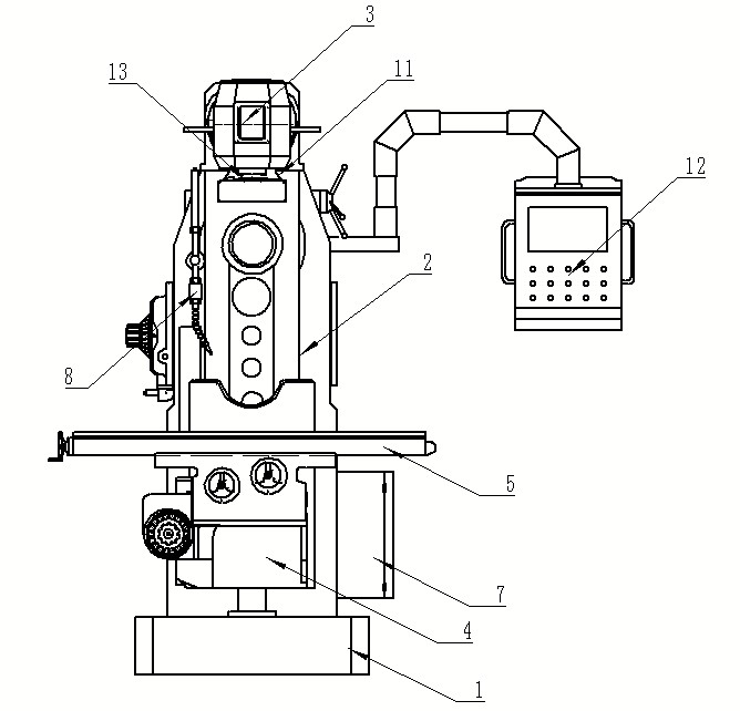
Figure 1 is a front view of a lift table milling machine with a large work table ram.
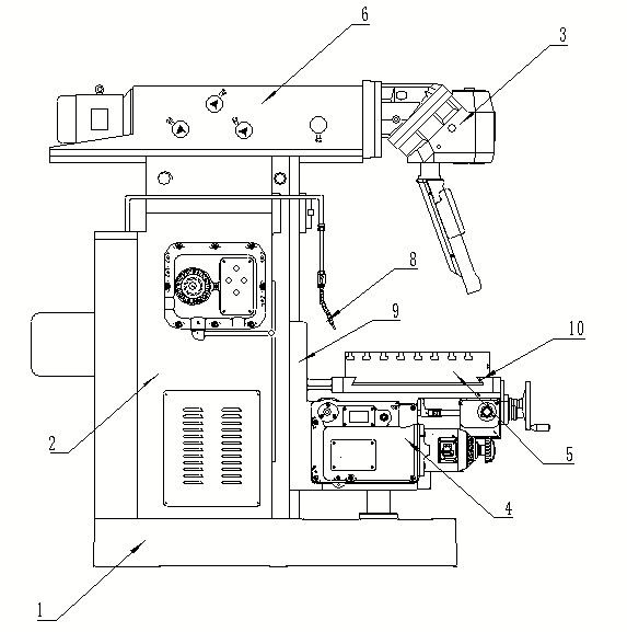
Figure 2 is a left view of a lift table milling machine with a large work table ram ride.
Figure 3 for the ram automatic feeding mechanism assembly diagram
The drawings are shown.
1 for the bed body, 2 for the base mechanism, 3 for the universal milling machine body, 4 for the lifting platform 5 for the table mechanism, 6 for the ram box body, 7 for the electrical box mechanism, 8 for the cooling mechanism, 9 For the vertical and horizontal dovetail rails, 10 for the longitudinal dovetail rails, 11 for the rams dovetail rails, 12 for the operation box mechanism, 13 for the ram automatic feed mechanism, 13-1 for the power gear, 13-2 for the transmission gear, 13- 3 for the spline shaft, 13-4 for the feed gear, 13-5 for the screw flange, 13-6 for the support seat, 13-7 for the ball screw, 13-8 for the screw seat.
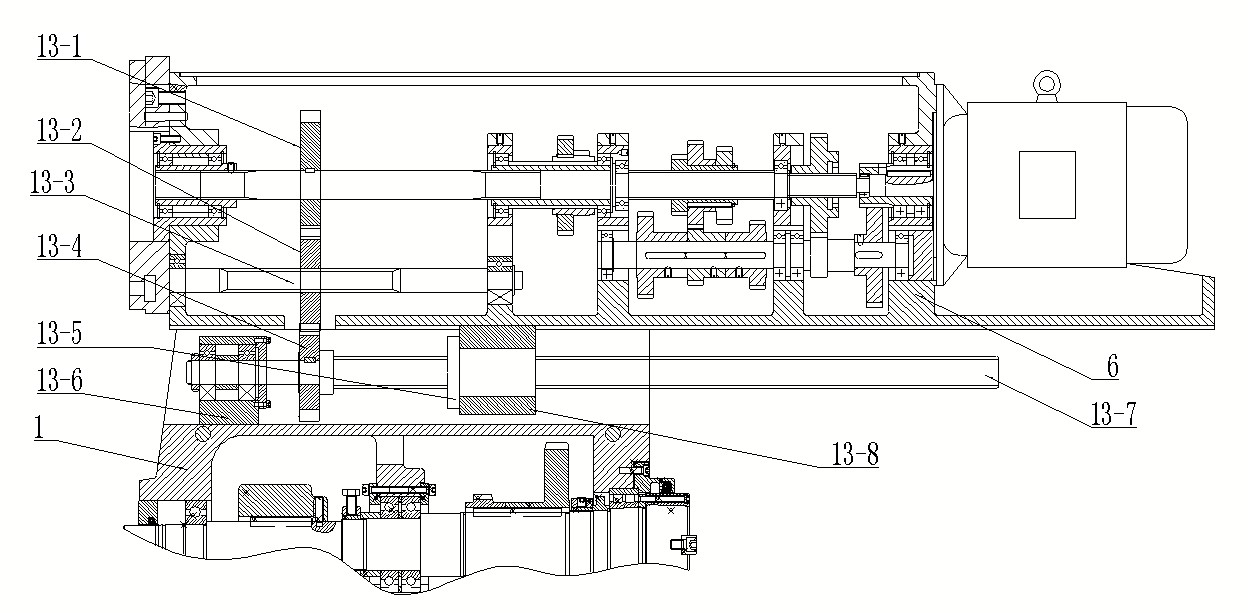
Through the two pairs of gear meshing power transmission to the bottom of the ball under the ball screw, the ball screw drive to drive the front and rear movement of the box. In the side of the pillow box is equipped with a handle seat, through the handle seat rotation can make the box in the spline shaft gear and the main drive gear in the ram box to achieve the combination and disengagement, can effectively control the ram feed.